Developer Onboarding Guide
- Philip Garrison (Deactivated)
- Chongsun Ahn (Unlicensed)
Who this is for / How to use this
This guide is for implementation developers who will be deploying, maintaining, and/or improving Casper (e.g. TZ eLMIS developers). This document has five parts:
Everyone should read the overview section. Then, you should use the following sections based on what your goals are.
Overview of the Casper Demo
The current Casper demo has code in the following git repositories:
- openlmis/openlmis-deployment - Used for provisioning Amazon Web Services (AWS) resources.
- openlmis/casper-deployment - Defines jobs in its
.gitlab-ci.ymlwhich deploy the five pieces of the Casper architecture - openlmis/casper-elmis - Used for compiling eLMIS and packaging it into a Docker image
- openlmis/casper-pipeline - The "real work" of Casper is done by the pipeline, which connects eLMIS v2 to OpenLMIS v3, transforming data along the way
- villagereach/openlmis-config - Holds configuration files (i.e.
settings.envfiles) which hold secrets (e.g. API access tokens, passwords)
Deployment is done from the master branch of each repository. Three of the repositories are hosted on Gitlab, instead of Github, primarily so that we can use Gitlab instead of Jenkins to run the deployment jobs.
In addition, eLMIS is deployed from the elmis-tzm/open-lmis repository, and OpenLMIS v3 is deployed via the openlmis/openlmis-ref-distro repository.
The five pieces of the Casper architecture are deployed on three AWS EC2 instances, as shown in the following diagram:
        casper-elmis.a.openlmis.org  casper.a.openlmis.org  casper-superset.a.openlmis.org
                      ↓                        ↓                       ↓
               ┌─────────────────┐    ┌─────────────────┐    ┌─────────────────┐
               |    eLMIS v2     |    |                 |---→|  v3 Reporting   |
               |-----------------|    |   OpenLMIS v3   |    |-----------------|
               | Casper pipeline |---→|                 |    |  NiFi Registry  |
               └─────────────────┘    └─────────────────┘    └─────────────────┘
                      ↑                                                ↑
        casper-elmis.a.openlmis.org:8080/nifi          casper-nifi-registry.a.openlmis.org
The eLMIS instance is deployed on the same machine as the Casper pipeline, which collects data from it. The NiFi registry is deployed on the same machine as the OpenLMIS v3 reporting stack, since the NiFi registry is only used by the reporting stack (the Casper pipeline is built on NiFi, but it doesn't use the registry).
Key Technologies Used
- Docker and docker-compose - These are perhaps the most important tool for deploying Casper. I highly recommend reading both of the linked guides. Each of the five components used by the Casper demo is defined by a single
docker-compose.ymlfile. Each docker-compose file in turn lists between 1 and 17 docker containers used by that component.- eLMIS: docker-compose.yml
- Casper pipeline: docker-compose.yml
- OpenLMIS v3: docker-compose.yml
- v3 reporting stack: docker-compose.yml
- NiFi registry: docker-compose.yml
- NiFi - This is the primary piece of the Casper pipeline, and it is also used by the v3 reporting stack. The NiFi transforms in the Casper pipeline are what turn data in v2's format into data for v3's format. NiFi (and the rest of the pipeline) does "stream processing": the NiFi process is always waiting and listening for new input data (from v2), which is transformed (into v3 data) and passed forward as soon as it is received, without waiting for more data. I recommend starting to read the linked NiFi guide, though it may be more useful to looking things up as you need them. More details are below in the "How the Casper Pipeline Works" section
- Terraform (and Ansible) - Terraform is used for creating resources on AWS. Those resources include servers (EC2 instances), domain names, databases, firewalls, and more. These resources are all defined by our terraform code, an approach known as "infrastructure as code". Though terraform is used to set up servers for the Casper demo, it terraform would not work with NDC servers.
Additional Technologies Used
- OpenLMIS v3
- TODO: what should we link here ?
- OpenLMIS v3 reporting stack
- Kafka - Along with NiFi, Kafka is used to drive the Casper pipeline. Each change to the v2 database becomes a message on a Kafka topic, and NiFi outputs transformed data as messages to other Kafka topics
- Debezium - Streams data from eLMIS into Kafka
- Superset - The data visualization web app that is the user interface for the OpenLMIS v3 reporting stack
- AWS - The Casper demo is entirely hosted on Amazon's cloud services, managed by Terraform
- Grafana - We run this application for monitoring the Casper pipeline to view statistics about Kafka and NiFi
How to provision and deploy
The diagram in the "Overview of the Casper Demo" section shows how the the five components of the demo are deployed to three servers. The goal of this section is to provide instructions for setting up all of the parts in that diagram.
Provisioning
This part of the guide assumes that you are using AWS to host everything and have and AWS account with IAM credentials (an access key ID and a secret access key). Provisioning AWS resources for the Casper demo is done through the, using our Terraform configuration.
Installation should be done on a machine that will control the targets. This is most likely your development computer.
Setup
- Install the Terraform command line v0.11 on your development computer
- Install ansible on your development computer
- Note that installing on OSX has been reported to be tricky. You should use virtualenv otherwise errors seem to be likely. This guide is useful for OSX users. Use Python 2.x, not 3.x. When using a virtualenv, do not use
sudo pip install, instead drop thesudowhich allows pip to install ansible in the virtualenv. mkvirtualenv olmis-deploymentif you need a new virtual environment.
- Note that installing on OSX has been reported to be tricky. You should use virtualenv otherwise errors seem to be likely. This guide is useful for OSX users. Use Python 2.x, not 3.x. When using a virtualenv, do not use
- Install pip, a package manager for Python
Install the requirements for our Ansible scripts:
$ pip install -r ../ansible/requirements/ansible.pip- Clone the openlmis-deployment git repository
$ git clone https://github.com/OpenLMIS/openlmis-deployment.git
Running Terraform
You will have to repeat these steps for each of the three machines used for the deployment. (It would be possible to put all the resources in a single terraform environment, but this way they can be managed separately.)
Set up your AWS access keys.
$ export TF_VAR_aws_access_key_id=$AWS_ACCESS_KEY_ID
$ export TF_VAR_aws_secret_access_key=$AWS_SECRET_ACCESS_KEY
Go to one of the three subdirectories of the openlmis-deployment/provision/terraform/casper/ directory (e.g. v2/ for the server with eLMIS and the pipeline).
$ cd openlmis-deployment/provision/terraform/casper/v2/
Prepare terraform (this creates the
.terraformdirectory):$ terraform init
- Start up the resources defined in the current folder. Or, if they are already running (e.g. if you are using the VillageReach AWS account), apply changes from any edited files. This command will ask for confirmation before actually making changes:
$ terraform apply
- You should be able to check that the newly created resources are working by pinging them, even though no applications are deployed yet e.g.:
$ ping casper-elmis.a.openlmis.org
Deployment
Casper is deployed via jobs on Gitlab. These jobs are defined in the .gitlab-ci.yml file. Each of the five components of the Casper demo have their own deployment job(s) – even though some are deployed to the same virtual machine, they have distinct deployment jobs. To redeploy a component, log in as a Gitlab user with appropriate permissions, and navigate to the jobs page of our casper-deployment repository. Below is a screenshot of one job from that page:

There are six main jobs available:
- v2 build - compiles eLMIS from the source code and saves the result on the
casper-elmis.a.openlmis.orgserver - v2 deploy - starts up the eLMIS web app using the result of "v2 build"
- The parameter "keep"/"wipe" determines whether the eLMIS PostgreSQL database is wiped
- pipeline deploy
- the persist/reset parameter determines whether Redis is reset
- v3 deploy
- the keep/wipe parameter affects which spring profiles are loaded; selecting "keep" should allow the v3 PostgreSQL state to remain
- nifi-reporting deploy - deploys the reporting stack
- nifi-registry deploy
Note: All of these deployment jobs authenticate to the servers using keys set in the continuous deployment settings page
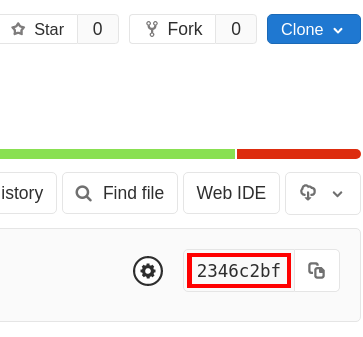
Select the job you want from the list, and confirm that the commit hash (highlighted in red on the left in the screenshot above) matches the latest commit in the casper-deployment repository. (Every version of the .gitlab-ci.yml is saved, so if you select a job with a different hash, you could be getting an outdated version of the deployment job.) That is, make sure that the commit hash is the same as the one shown on the homepage:
How to operate and monitor
...
TODO: something on Scalyr?
Is it running?
- eLMIS: the sign-in page should load at https://casper-elmis.a.openlmis.org (though beware of browser caching)
- Pipeline:
- NiFi should load at http://casper-elmis.a.openlmis.org:8080/nifi
- Kafka Topics UI should load at http://casper-elmis.a.openlmis.org:8000/
- Grafana should load at http://casper-elmis.a.openlmis.org:3000
- OpenLMIS v3: the sign-in page should load at https://casper.a.openlmis.org
- NiFi registry: should load at http://casper-nifi-registry.a.openlmis.org:18080/nifi-registry/explorer/grid-list
- v3 Reporting stack: Superset should load at http://casper-superset.a.openlmis.org
For more detailed debugging, one option is to log in to one of the EC2 instances and run docker ps -a to list all running and stopped containers – stopped containers are often signs of trouble, though the "config" or "setup" containers are supposed to exit after doing their work during the deployment.
Passwords
Below are the default passwords of the various services. The format of the following credentials is username | password
- eLMIS
StoreInCharge | Admin123Admin123 | Admin123
- Pipeline
- Kafka, NiFi are unsecured (take care to not make these public in production)
- Grafana:
admin | admin(must be changed on initial login)
- OpenLMIS v3
StoreInCharge | passwordAdmin123 | password
- NiFi Registry: unsecured (take care to not make this public in production)
- Reporting stack
- Superset uses OpenLMIS v3 to log in, e.g.
Admin123 | password
- Superset uses OpenLMIS v3 to log in, e.g.
Monitoring with Grafana
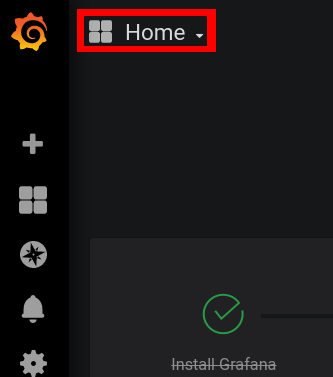
The Casper pipeline has been set up to log some statistics for monitoring with Grafana. Kafka stores this data in a Prometheus database, and NiFi stores this data in an InfluxDB database. Grafana connects to both of these, and can display it in all sorts of types of charts. Two sample dashboards have been set up for now, one for Kafka and one for NiFi. To use them, open grafana at casper-elmis.a.openlmis.org:3000, and log in. (Whenever the pipeline is redeployed, grafana returns to the default credentials admin|admin, which you are then prompted to change on the first login.) To get to the dashboards, click the dashboard selector in the top-left, which defaults to "Home":
The most useful part of the Kafka dashboard is probably the "Messages per topic" chart, which counts how many pieces of data have gone through the pipeline over time, both coming from v2 and going in to v3. In the NiFi dashboard, each of the five data transforms (more on this subject in the following section) has a chart, which shows the average time taken for data to go through that transform. If it seems that it is taking a long time for data to move from v2 to v3, these charts can help you identify whether NiFi is the bottleneck.
How the Casper Pipeline Works and NiFi Intro
              ┌──────────────────┐                             ┌─────────────────┐
              |    eLMIS's       |                             |     v3's        |
              |   PostgreSQL     |                             |   PostgreSQL    |
              ├──────────────────┤                             └─────────────────┘
              |    Debezium      |                                     ↑
              └──────────────────┘                                     ↑
                       ↓                                               ↑
              ┌──────────────────┐     ┌─────────────────┐     ┌─────────────────┐
              |Postgres Connector| → → |  Kafka Connect  | → → | JDBC Connector  |
              └──────────────────┘     | ┌─────────────┐ |     └─────────────────┘
                                       | |    Kakfa    | |
                                       | |             | |
                                       └─┴─────────────┴─┘
                                              ↓   ↑
                                       ┌─────────────────┐
                                       |     *NiFi*      |
                                       └─────────────────┘
                                              ↓   ↑
                                       ┌─────────────────┐
                                       |      Redis      |
                                       └─────────────────┘
The diagram above shows the path that data takes through the Casper pipeline. Whenever a change is written to the eLMIS database, Debezium picks it up immediately (as soon as it's in the write-ahead log) and stores it in a Kafka topic for incoming data (via the Kafka Connect abstraction). This doesn't require any modification to eLMIS, just read access to the database's write-ahead log. NiFi is the piece that does the data transformation – when the message is posted to the Kafka topic, Kafka sends it to NiFi, which interprets the change to the v2 database and maps it to the proper change in the v3 database. NiFi caches some data in Redis to keep track of its work – only temporary, queued data is stored in NiFi. When NiFi finishes, it publishes the transformed data to a Kafka topic for outgoing data. Kafka then sends that message to the Java Database Connectivity (JDBC) connector, which writes the new change to the v3 database.
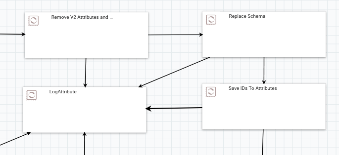
To understand better what's going inside NiFi, visit http://casper-elmis.a.openlmis.org:8080/nifi and explore the processors that are set up there; double-click on a process group to navigate inside, and use the bar at the bottom to navigate back up (reading this NiFi documentation will provide good background). Some of the processes in NiFi look like the image below (I've zoomed out here to hide extraneous details). Each piece of data that comes in to NiFi will follow paths defined by the arrows between the processors. In the example in the image, the arrows going in to the LogAttribute processor are only taken when a processor encounters an error; the path that each data piece will hopefully take in this image is ... → "Remove V2 Attrbutes and Set Defaults" → "Replace Schema" → "Save IDs to Attributes" → ... . Each arrow in NiFi is actually a queue; if a processor is working more slowly than data is coming in to it, the processors before it can still do work until that queue is full.
Transformations in NiFi
The Casper pipeline can be described as an extract-transform-load (ETL) process. NiFi acts as the main component for the transform step. The NiFi system contains multiple components (called "process groups") that each transform one eLMIS/v3 table. These transform process groups hold one or more sub-components, each of which do part of the work of the overall transformation by processing data that comes into it. The sub-components are connected together in a directed graph configuration, creating a data flow. These sub-components, which can either be more process groups or individual processors, either do transform work or do work in helping with transforms. NiFi comes with a myriad of different processors to help process data in many ways.
The data format of the message that comes out of Debezium into the Kafka topic (through the Postgres Connector) is JSON for both the key and the value. The exact JSON format for each has two parts:
- Schema - the structure of the data in the payload, meaning it will list all of the properties in the payload and their types
- Payload - the actual data of the message
In order for this message to be properly consumed by the JDBC Connector into the v3 system, this JSON needs to be modified/transformed. This is where NiFi comes in with its transform process groups.
Each transform process group can generally be divided into these main parts for each table row:
- Consume any new stream messages from the corresponding eLMIS Kafka topic
- If the stream message is delete, do delete processing
- Assign an ID to the row, either by generating a new ID, or using an already existing ID
- Replace schema and payload in the Kafka key and schema in Kafka value, from eLMIS to v3
- Modify the payload in Kafka value, from eLMIS to v3
- If the row has a parent, wait until parent already exists
- If necessary, map any reference data identifiers (programs, facilities, etc.) to their corresponding v3 UUIDs
- If necessary, convert any eLMIS epoch "dates" to v3 dates
- Publish the row to a stream message to the corresponding v3 Kafka topic
- Save the row ID to the cache and perform any related metadata tasks
Details about each part of a transform process group are below.
Consume from Kafka Topic
Each eLMIS table has a corresponding Kafka topic that starts with original, as specified in the Postgres connector. The NiFi processor is configured to monitor that Kafka topic and consume any new messages streamed to that topic, with the key data put into the FlowFile's kafka.key attribute, and the value data put into the FlowFile's content. (NiFi represents each piece of "User Data" as a FlowFile.)
(If Delete) Do Delete Processing
Some stream messages represent a delete, which means the row (and any children) should be deleted. Kafka Connect only recently (in Confluent's v5.3) supports delete in its JDBC sink connector. However, this does not automatically delete the children, as v3 currently does not set most foreign keys as ON DELETE CASCADE. To get around this without submitting widespread changes to OpenLMIS v3 Core, we delete manually in NiFi. This is set up by having the overall parent transform execute SQL to delete the row in the table and all child tables, and having the child transforms do nothing if it finds a delete.
Assign an ID
The ID of the row is mapped to its corresponding v3 UUID. This is done by checking if a mapping already exists in the cache. If so, the mapping UUID is used; otherwise, a new UUID is "generated" to be used and saved to the cache. Note: the NiFi FlowFile filename attribute is used as the "generated" UUID.
Replace Schema and Payload in Key and Schema in Value
The entire eLMIS schema and payload is stored in the kafka.key attribute, so this is replaced with the v3 schema and payload, with the key ID assigned from the one found in the previous step.
Then, the entire schema in the Kafka Value is replaced with a v3 schema.
Note: this step could be improved by replacing the schemas from a v3 "schema registry" rather than hardcoded into the processor
Modify the Payload in Value
This is done using Jolt to transform the JSON in several ways:
- The eLMIS fields that are not used in v3 are discarded
- The eLMIS fields that have a different name in v3 are mapped to the new name
- Some eLMIS values are replaced/mapped. Example: requisition status RELEASED_NO_ORDER replaced with RELEASED_WITHOUT_ORDER.
Note: eLMIS has a fullsupply boolean for requisition line items, but the closest field in v3 is nonfullsupply, so this step toggles the field value.
(If Necessary) Wait for Existence of Parent
This step applies if the row depends on the existence of a parent (e.g. requisition line item depends on a requisition). This process group checks that the parent exists in the v3 database, and does not continue in the transform process until it exists. It does this by checking the cache. Once the parent exists in the v3 database, its UUID is saved in the cache.
(If Necessary) Map Reference Data Identifiers
If the row points to identifiers in reference data (program, facility, product, etc.), each FlowFile maps those identifiers to their v3 mappings. These identifiers may not necessarily be IDs or UUIDs; for instance, product is mapped by product codes.
(If Necessary) Convert eLMIS Dates to v3 Dates
Some tables in eLMIS have datetime fields. These are stored as timestamps, which are then numbers representing milliseconds from Unix Epoch. These are converted to v3 ISO dates.
Publish to Kafka Topic
Each v3 table has a corresponding Kafka topic whose name matches the table in v3 (e.g. for requisitions, it would be requisition.requisitions). The NiFi processor takes the FlowFile content, which is modified JSON, and publishes it to the Kafka topic, to be consumed by the JDBC connector.
Save New Row to Cache
The new row being added to the v3 database has its UUID cached, so that any children dependent on it can find the mapping. Additionally, for the requisitions transform, related metadata (requisition permissions and stock adjustment reasons) are updated.
Strategies for Building NiFi Transformations
When Working in a Streaming Data Flow
Things to keep in mind:
- No guarantee of order, so some processing may need to be done to ensure things are synced in the correct order.
- The domain-driven design (DDD) concept of an aggregate root is not done here in one transformation. For example, a requisition is an aggregate root, but all of its children (line items, status changes, etc.) are handled in separate streams. Things were not aggregated in the transform step because the v3 database backend is relational, so those children are already in separate tables.
Mapper Transformations
- Mapping a field name A → B (e.g. requisition_line_items, rnrid → requisitionid)
- NiFi processor to use: JoltTransformJSON
- NiFi processor to use: JoltTransformJSON
- Mapping a field value A → B (e.g. requisitions.status, RELEASE_NO_ORDER → RELEASE_WITHOUT_ORDER)
- NiFi processor to use: JoltTransformJSON
- NiFi processor to use: JoltTransformJSON
Filter Transformations
- Discarding a field (e.g. requisitions.clientsubmittednotes not present in v3)
- NiFi processor to use: JoltTransformJSON
- Discarding a row (no examples in the current transformations)
- Validation (no examples in the current transformations)
- Normalization (no examples in the current transformations)
ID Replacement Transformations
- Replace an ID with another (e.g. replacing eLMIS serial ID with v3 UUID)
- NiFi processors to use: ReplaceText or ReplaceTextWithMapping
- See process groups such as "Convert ID" or "Map Programs"
Aggregator Transformations
- Add known values from source B not present in source A (e.g. setting requisitions.templateid from v3 database)
- Nifi processor to use: JoltTransformJSON
- See "Remove V2 Attributes and Set Defaults" processor in "Transform Requisitions V2 To V3" process group
- Nifi processor to use: JoltTransformJSON
- Join data into aggregate roots (no examples in the current transformations)
Related content
OpenLMIS: the global initiative for powerful LMIS software